
SDAPO
Factory focus on PoE Switch , PoE Module , PoE Splitter , PoE Injector , PoE Cable.
Factory focus on PoE Switch , PoE Module , PoE Splitter , PoE Injector , PoE Cable.
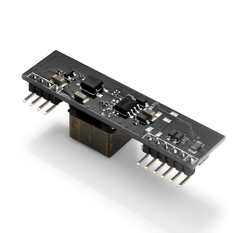
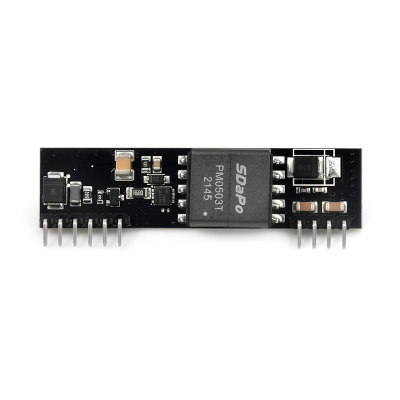
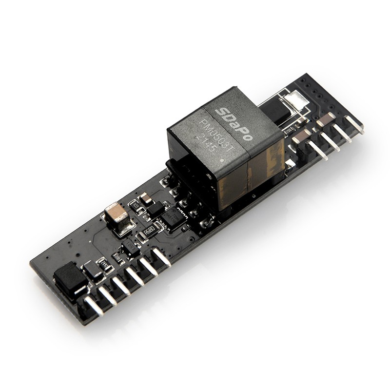
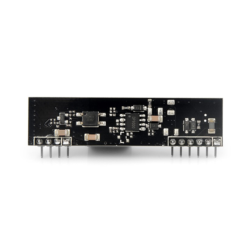
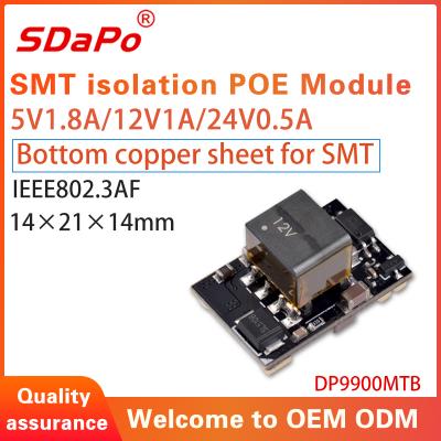
POE board IEEE802.3af 5V2.4A POE module SDAPO DP9200
Products Description
You are welcome to customize the POE modules of various sizes and appearances and function.The layout is required to receive the initial research and development expenses.After ordering a certain number of modules (usually 5000 pieces), the r&d cost can be deducted.After the sample is qualified, batch production.
DESCRIPTION
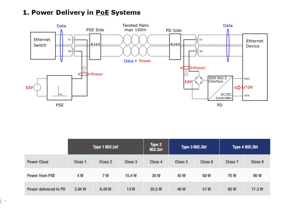
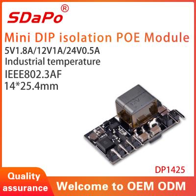
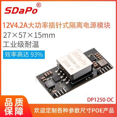
5V, 13W PD(Powered Device) Integrated Module (Isolation Type)
FEATURES
* Fully supports IEEE802.3af
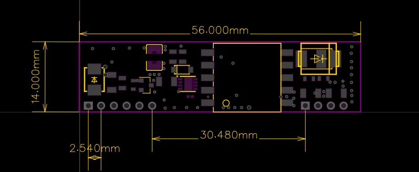
* Small Single In-Line (SIL) package size –56mm (L) x 14mm (H)
* Input Voltage Range 37V to 57V
* Support PoE applications in both of Fast / Gigabit Ethernet environments.
* Short Circuit Protection
* Over-temperature Protection
* Programmable Classification (Default:Class 0)
* High Efficiency
* Isolation level 1.5KVrms.
* Easy Installation and Low Cost (Isolation Type, Minimum External Devices required)
* Low Output Ripple and Noise
* Adjustable Output Voltage
* 1500Vrms Isolation (Input-Output)
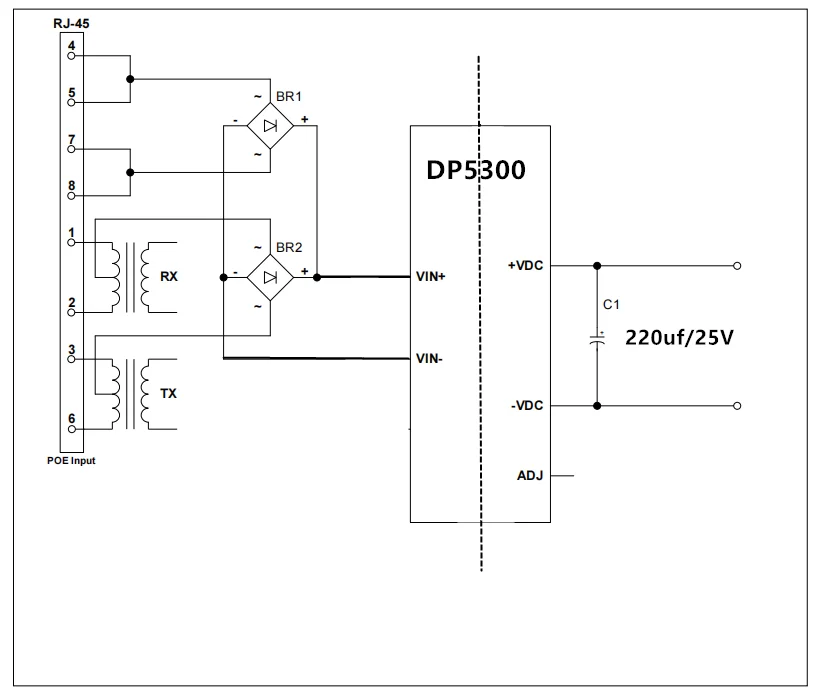
PIN ASSIGNMENT
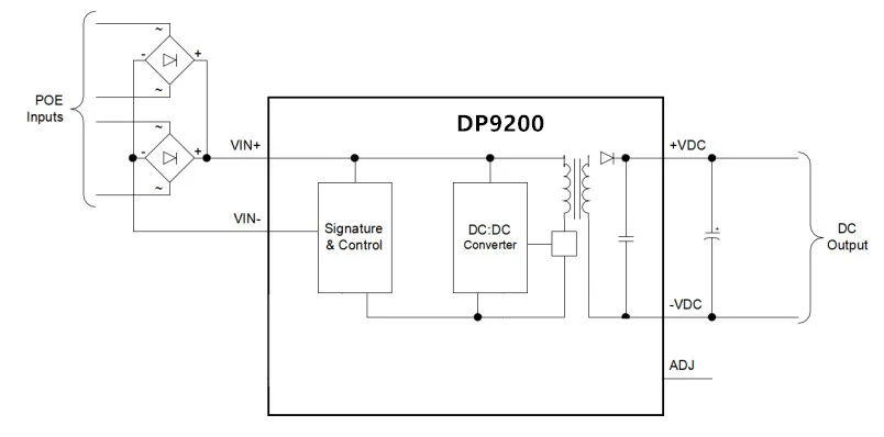
TYPICAL SYSTEM DIAGRAM
TEST DATA
ELECTRICAL SPECIFICATIONS
Contact: Vivian Xiao
Phone: 0086-13724329562
E-mail: 2851558131@qq.com
Add: 3F, Building 5, Zone A, No.2, Yanhe Road, Xinsheng District, Longgang Street, Shenzhen, China
 Send Email
 Vivian
 Vivian
 SDAPO
SDAPO